
Leak Testing Case Studies: Fuel Tank Leak Testing
Explore the Leak Testing Section
Leak Testing is used to ensure quality, tested and proven parts are supplied into the market. The use of leak testing equipment eliminates failures in the field.
Explore this section to find out more about the how TQC can help you with your leak testing requirements
- Overview
- Air Decay
- Helium
- Other Test Methods
- Leak Testing Services
- Standard Equipment
- Case Studies
- Automotive Brake Leak and Flow Testing
- Automotive Bedplate Leak Test Machine
- Battery Tray Leak Test Machine
- Chilled Beam Leak Test
- Flexible Leak Test Facility
- Fuel Tank Leak Testing
- Helium Leak Test Bench
- Helium Leak Testing of Automotive Fuel Pipes
- High Pressure Audit Leak Testing System with Datalogging
- High Speed Leak Testing of Pipe Fittings using Air and Helium
- High Speed Leak Testing of Plastic Vial for the Medical Industry
- Leak Test Facility for Water Valves
- Leak Test Cell with Robotic Handling
- Casting Leak Testing of Engine Blocks
- Medical Filter Leak Test Machine
- Medical Showerhead Leak Test Machine
- Plastic Fuel Rail Leak and Burst Test Machine
- Plastic Sump Pipe Leak Test and Assembly
- Small Medical Device Leak Test Machine
- Twin Station Leak Test Machine for Oils Sumps
- V6 Cylinder Head Leak Test Machine
- V6 Engine Leak Test Machine
- V8 Cylinder Head Leak Test Machine
- V8 Engine Block Leak Test Machine
- Valve Block Leak Test Machine
- Vauxhall Leak Test Machine
- Weapon Leak Test Machine
Client: Tier 1 Multi National Car Manufacturer
Part: Fuel Tanks
Machine supplied: Helium leak test system with functional test and conveyor system
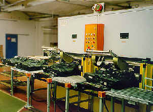
Overview: This system was designed and manufactured in order to give the customer the ability to test fully assembled plastic fuel tanks within their production environment. TQC developed this system alongside the client to allow them to helium leak test and then check the rollover check valves and the float sensor.
Download details of this system as a PDF
Helium leak testing for fuel tanks - mass spectrometer dry test
TQC has specialised in the automatic helium leak testing of components for many years. Fuel tanks have previously been regarded as a leak testing problem - the volume is unstable and too large for air decay testing. Water dunk testing is operator dependent and causes longer term damage to the unpainted tank. Neither method will detect a fine vapour leak.
- Quantifiable leak testing
- Calibration to ISO 9000
- Fast, clean and dry test
- High sensitivity
- Automated pass/fail limits
- No drying costs and no tank water damage
Now proven by several installations, TQC is able to supply Fuel Tank Leak Testing using Helium. The system provides a fast reliable dry test with numerical leak results. The sensitivity is equivalent to a "dunk tank bubble" once in several days. Connections to the tank are made automatically, the system is self-monitoring and the operator may be unskilled. The system is suitable for leak testing metal or plastic tanks.
Typical specification for a 75 litre plastic fuel tank is:
| Throughput | 48 second cycle (twin station unit) |
| Test Pressure | 200mbar (3psi) |
| Pass / fail limit | 10-4 mbarl/sec (0.1mm3/sec) |
| Helium usage | approx 8000 tanks/standard cylinder |
The Pressure Sequence
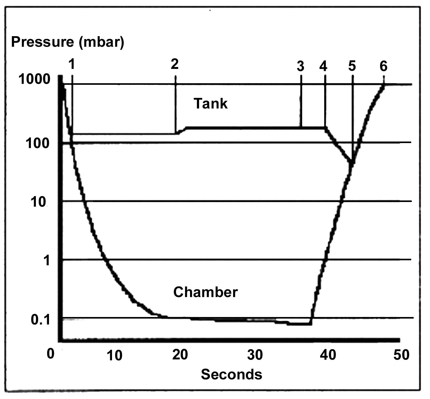
1. Pump chamber and tank
2. Dose tank when chamber reaches 0.1mbar
3. Enter measure phase
4. Evacuate helium from tank. Vent chamber
5. Vent tank and chamber
6. Test complete
Description
- The fuel tank is placed in a supporting cradle which slides into a stainless steel chamber.
- Operator controls close a safety shielded chamber door.
- The sequence is automatically started by the door closure.
- The chamber and tank are pumped down together to a pressure of 180mbar, at which point the tank is isolated from the chamber.
- The chamber pressure is further reduced to less than 0.1 mbar, during which time the tank pressure is monitored to check for a gross leak.
- A 10% concentration of helium is dosed into the tank, allowed to disperse, and the chamber is sampled for leakage using a mass spectrometer.
- After the test, the helium is evacuated, the chamber and tank are vented together to atmosphere, and the door is opened automatically. Results are then logged for SPC analysis.
Vehicle Fuel Systems: Legislation
Total vehicle and component assemblies are subject to a variety of fuel loss legislation requirements. Both US and EC evaporative emmissions requirements are the subject of continued revision and it is advised that the current USA Californian certification standard be adopted as the basis for vehicle component and assembly production acceptance.
TQC have also included helium reuse and recovery systems to reduce helium consumption to less than 1% of a total loss system.
To find out more about how we can help you with your leak testing requirements:
We build all machines in-house, applying our 25+ years experience in specialised test and automated handling machines experience to the engineering projects we undertake. We offer customer support, backup and service call-out for all projects, whatever the size.
Get in touch with us to discuss your requirements and we will be happy to offer our professional advice and visit you at your site.
- Contact us online
- Email us or call us on 0115 950 3561