Leak Testing: Novel Leak Testing Techniques
Explore the Leak Testing Section
Leak Testing is used to ensure quality, tested and proven parts are supplied into the market. The use of leak testing equipment eliminates failures in the field.
Explore this section to find out more about the how TQC can help you with your leak testing requirements
- Overview
- Air Decay
- Helium
- Other Test Methods
- Leak Testing Services
- Standard Equipment
- Case Studies
- Automotive Brake Leak and Flow Testing
- Automotive Bedplate Leak Test Machine
- Battery Tray Leak Test Machine
- Chilled Beam Leak Test
- Flexible Leak Test Facility
- Fuel Tank Leak Testing
- Helium Leak Test Bench
- Helium Leak Testing of Automotive Fuel Pipes
- High Pressure Audit Leak Testing System with Datalogging
- High Speed Leak Testing of Pipe Fittings using Air and Helium
- High Speed Leak Testing of Plastic Vial for the Medical Industry
- Leak Test Facility for Water Valves
- Leak Test Cell with Robotic Handling
- Casting Leak Testing of Engine Blocks
- Medical Filter Leak Test Machine
- Medical Showerhead Leak Test Machine
- Plastic Fuel Rail Leak and Burst Test Machine
- Plastic Sump Pipe Leak Test and Assembly
- Small Medical Device Leak Test Machine
- Twin Station Leak Test Machine for Oils Sumps
- V6 Cylinder Head Leak Test Machine
- V6 Engine Leak Test Machine
- V8 Cylinder Head Leak Test Machine
- V8 Engine Block Leak Test Machine
- Valve Block Leak Test Machine
- Vauxhall Leak Test Machine
- Weapon Leak Test Machine
Novel Leak Testing Techniques
Novel techniques are described that can be used whilst still applying the basic principles of leak measurement to test a range of medical devices. Originally featured in Medical Device Technology June 2006
Finding the leak
It is unlikely that any container or barrier does not leak to some extent. This is because at one extreme any pressure differential is dissipated in fractions of a second, and at the other extreme the pressure is able to permeate across or through the barrier over tens or hundreds of years. To find a potential leak path or flow, an impetus has to be generated, that is, a change in pressure or partial pressure across the barrier. It must be remembered that for something to leak, the gas or liquid will pass from one side of the barrier to the other. This means that the leak can often be detected by a reduction in pressure or in gas or liquid concentration on one side of the barrier, or an increase in pressure or in gas or liquid concentration on the other side.
A previous article covered some of the basic testing techniques, including flow measurement, weight change, bubble detection, visual moisture detection, air-pressure decay or tracer gas testing. Here, some novel techniques are explained that, with some care, can be applied.
Sealed Parts

Leak tested vials with
glass bottle and plastic
tamper-evident caps
With sealed parts or containers such as swallowable devices, vials and blister packs (Figure 1) there is only access to the outside of the device. In this case, it is necessary to build a chamber around the part. Unfortunately, the instrumentation to detect small leakages is often too sensitive to detect gross leaks. Thus, techniques of timed or volume dosing are used to first check that the device does not have a large hole. Timed dosing, whereby the pressure is allowed to build up in a metered fashion is good for larger parts of over 100 mL. Below this volume, a volume dosing technique will have to be used. Timed dosing expects the pressure to have reached a particular value within a known time; if it has not, it must have leaked into the part. Volume dosing allows a known volume at a known pressure to be connected to the test chamber. If the unit under test has a massive leak, then the pressure will be different from that expected.
High-pressure Devices
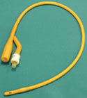
An example of a
three-ported catheter
to be leak tested
As the pressure employed as a test medium increases, it becomes more unstable for use within air-pressure decay. The pressures to be detected are typically in the range of Pascals, thus, the noise-to-signal ratio becomes poor because the signal is swamped by the background instability of the pressure. For this reason, it is often better to create a chamber outside a high-pressure part such as a catheter or other long intravenous devices (Figure 2) and then measure pressure differences at lower pressures. In this way, catheters that may have pressures of 52 bar can be tested. Sealing tubes with pressure at 52 bar is difficult and special high-pressure connectors are available that will seal over the ends of these types of catheters (Figure 3). Alternatively, high-pressure helium can be used within the device, but this can be an expensive testing method for high-volume products unless the helium is reused or reclaimed in some way.
Liquid-filled containers
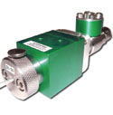
High-pressure connectors
are used when testing
catheters of 52 bar
Many medical devices contain or are packaged within a liquid; examples include some diagnostic units, disposable contact lenses and gel dispensers. The problem here is to find a leak-test technique that is not affected by the liquid plugging the leak path because liquid can easily plug a hole of 10–15 µm in size. A hole of this size in smaller parts is detectable by using air-pressure decay; but a leak can be detected only until liquid comes into contact with the opening of the hole. There are two other potential techniques that can be used to detect a leak path in these types of medical device. One employs helium leak detection because often the helium will find its way through the liquid. The other uses high vacuum and boils off liquid as it emerges from the leak path. Even when there is a small amount of liquid, this will create a massive amount of vapour if the pressure is sufficiently reduced. Typically at approximately 98% vacuum, water, alcohols and some oils will boil at ambient temperatures. By monitoring the pressure as the vacuum is applied, the corresponding graph (see below) will show that the curves are different for sealed and leaking parts. This has been demonstrated to work on liquid-filled blister packs containing contact lenses where the leakage of the fluid to the outside of the pack is the only way to detect leakage.
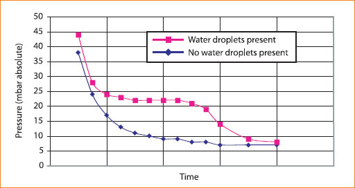
Pressure curves for the detection of water inside a leak path
High-speed Production Techniques
To detect leakage, it is necessary to wait until a change in pressure or its concentration is noticed. To speed up this process, it is possible to increase the pressure behind the leakage mechanism or use a sensitive technique such as a tracer-gas technique rather than air-pressure decay and operate at throughputs of 3600 parts/hour. A number of machines are capable of testing devices in cycle times of less than one second per part. These throughputs are normally achieved by testing multiple units at once. However, these machines can pose further issues related to tracer-gas usage and the need to reclaim the tracer gas.
Supplying the need
The issues described above are designed to give some insight into the need for novel techniques in testing for leakage. It has not been possible in this article to cover the techniques in detail. Further information and examples of employing the above techniques can be obtained by getting in touch with us.
To find out more about how we can help you with your leak testing requirements:
We build all machines in-house, applying our 25+ years experience in specialised test and automated handling machines experience to the engineering projects we undertake. We offer customer support, backup and service call-out for all projects, whatever the size.
Get in touch with us to discuss your requirements and we will be happy to offer our professional advice and visit you at your site.
- Contact us online
- Email us or call us on 0115 950 3561
