Leak Testing Case Studies: Helium Leak Testing of Automotive Fuel Pipes
Explore the Leak Testing Section
Leak Testing is used to ensure quality, tested and proven parts are supplied into the market. The use of leak testing equipment eliminates failures in the field.
Explore this section to find out more about the how TQC can help you with your leak testing requirements
- Overview
- Air Decay
- Helium
- Other Test Methods
- Leak Testing Services
- Standard Equipment
- Case Studies
- Automotive Brake Leak and Flow Testing
- Automotive Bedplate Leak Test Machine
- Battery Tray Leak Test Machine
- Chilled Beam Leak Test
- Flexible Leak Test Facility
- Fuel Tank Leak Testing
- Helium Leak Test Bench
- Helium Leak Testing of Automotive Fuel Pipes
- High Pressure Audit Leak Testing System with Datalogging
- High Speed Leak Testing of Pipe Fittings using Air and Helium
- High Speed Leak Testing of Plastic Vial for the Medical Industry
- Leak Test Facility for Water Valves
- Leak Test Cell with Robotic Handling
- Casting Leak Testing of Engine Blocks
- Medical Filter Leak Test Machine
- Medical Showerhead Leak Test Machine
- Plastic Fuel Rail Leak and Burst Test Machine
- Plastic Sump Pipe Leak Test and Assembly
- Small Medical Device Leak Test Machine
- Twin Station Leak Test Machine for Oils Sumps
- V6 Cylinder Head Leak Test Machine
- V6 Engine Leak Test Machine
- V8 Cylinder Head Leak Test Machine
- V8 Engine Block Leak Test Machine
- Valve Block Leak Test Machine
- Vauxhall Leak Test Machine
- Weapon Leak Test Machine
Client: Tier 2 Automotive Fuel Systems supplier
Part: Fuel Filler Pipe
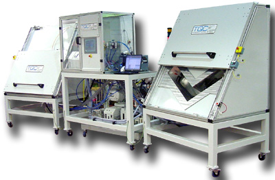
Machine supplied: Twin station (pendulum) helium leak test machine for automotive fuel pipes
Overview: This system was designed and manufactured in order to give the customer the ability to helium leka test fuel filler pipes within their production environment. TQC developed this system alongside the client to allow them to install leak test facilities in Portugal and a second unit in China.
Download details of this system as a PDF
TQC designed and manufactured 2 helium leak test systems for the automatic testing of plastic fuel pipes. The systems included bespoke tooling to accommodate 2 variants of fuel pipe.
The helium leak test machine is split into three modules:
- A Centre Module containing the primary controls (Touch screen HMI), vacuum pumps, mass-spectrometer, electrical cabinet, bar code printer and scanner.
- Two Test Modules, each containing pneumatically sealing test chamber and localised control and monitoring equipment.

The components are loaded independently into each test chamber, attaching onto the pneumatically expanding seal connector. As each component has three entry points, all of these must all be sealed prior to commencing testing using:
- A threaded sealing plug. This is screwed into the threaded insert within the fuel pipe assembly prior to loading the component into the test chamber.
- A mechanically operated expanding seal. This is fitted into the breather pipe within the fuel pipe assembly prior to loading the component into the test chamber. Ensure orientation does not restrict the location of the test component.
- A pneumatically operated expanding seal. This forms the primary insertion point/datum with the rubber hose on the fuel pipe assembly fitting over it. The seal is expanded automatically using an integrated pneumatic piston as part of the test cycle.
Once the part is sealed correctly, it is placed into the test chamber and over the pneumatically operated expanding seal. The lid is then pulled down over the test chamber to the closed position and the cycle start button operated for that chamber on the centre module HMI.
The part is sealed from the chamber and the chamber is sealed from atmosphere. The component is then evacuated to a pre-set level and held there for a time interval to monitor for any large leak created by the pressure differential (termed 'Gross Leak'). A fail at this point will reset the cycle.
If the test is passed then both the component and the chamber are evacuated to a lower pre-set level. A fixed volume of Helium is then injected into the component producing a 140mBar pressure differential between the component and chamber. The chamber vacuum line is switched to the mass-spectrometer which monitors for helium leakage from the component into the chamber (termed 'Fine Leak').
A label printer will dispense the appropriate label based upon the data entered by the operator if the test was successful. This is scanned using a hand-held barcode reader for verification.
Any components that fail due to gross or fine leaks are held for leak location.
The leak location test requires the component to be evacuated, then filled with Helium at 1140mBar Absolute (to produce the 140mBAR pressure differential above atmospheric) A hand-held sniffing probe is connected to the mass-spectrometer and used to manually locate helium concentrations indicating leaks in the test component.
- Contact us online
- Email us or call us on 0115 950 3561
